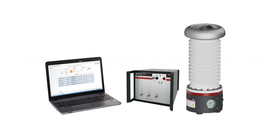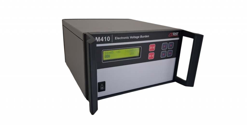
Electronic Voltage Burden

Electronic Voltage Burden M411 is an advanced, programmable load simulator designed for the secondary circuits of voltage transformers during testing, verification, and calibration. Featuring a broad programmable power range, it effortlessly accommodates standard burdens defined by national and international regulations, as well as custom user-defined values
FEATURES AND BENEFITS
- Range of burden power values for VT in accordance with standards: IEC 61869-3,
IEC 61869-5, IEC 60044-2, IEC 60044-5, IEEE C57.13 - A wide load range of up to 1200 VA allows the M411 to be used as a single device (monoblock) without additional power range extenders
- Standard and non-standard values of burden power with standard and non-standard rated secondary voltages
- Extended range of rated voltage factor FV up to 2,5
- 100 % and 25 % rated burden power, cos φ = 0,8 at rated frequency 50 and 60 Нz
- 100 % and 0 % rated burden power, cos φ = 1 at rated frequency 50 and 60 Нz
- Resistance compensation of the cable used for connect to the secondary winding
- Connection to two taps of a multiple-tapped winding
- The ability for the user to create his own range of frequently used burden values makes operation simple
- Possibility of using with automated VT calibration systems
- Ensuring safe operation with continuous voltage monitoring
- Protection against user setting errors, overvotage and overheating
- Simple use by intuitive user interface
- Integrative 5,7’’ touch screen
COMPLETE TEST SYSTEM
Integrating the M411 into a computer-controlled test system is enabled by combining it with:
- M100 Comparator
- M120 Voltage Transformer Test Set
- S250 High-Voltage Source
APPLICATIONS
Electronic Voltage Burden M411 is used by:
- Manufacturers of Voltage Transformers
- On-site testing of Voltage Transformers
- Calibration laboratories
- Metrology institutes
|
Rated burden voltage USr , V |
Rated voltage factor FV |
Rated burden power Sr , VA |
Power factor, cos φ |
Rated frequency fR, Hz |
| 100/3…150/3 |
1,2 |
1,25…600 | 0,8 | 50; 60 |
|
1,9 |
1,25…500 |
|||
|
2,5 |
1,25…100 |
|||
| 1…10 |
1 |
|||
|
150/3…200/3 100/√3…120/√3 |
1,2 |
1,25…1200 | 0,8 | |
|
1,9 |
1,25…500 | |||
|
2,5 |
1,25…100 |
|||
| 1…10 |
1 |
|||
|
200/3…240/3 120/√3…415/√3 100…240 |
1,2 |
1,25…1200 | 0,8 | |
|
1,9 |
1,25…500 |
|||
| 1…10 |
1 |
|||
|
115/√3; 120/√3; 115; 120 |
1,5 |
12,5 |
0,1 | |
|
35 |
0,2 |
|||
| 25 |
0,7 |
|||
| 75; 200; 400 |
0,85 |
| Secondary voltage range US | 0,02·USr…FV·USr |
| Active and reactive power errors | ± 0,03·S* |
|
Power mains Rated voltage Rated frequency |
100…240 V 50/60 Hz |
|
Operating temperature Relative humidity |
0…40 °C up to 80 % non-condensing |
| Size (W × H × D) | 460 × 285 × 460 mm |
| Weight (Main unit) | 35 kg |
|
Standards Safety EMC |
EN 61010-1:2010 EN 61326-1:2013 |
* Setted burden power value.
** The manufacturer reserves the right to change the characteristics of the device.