Comparator

Comparator M100 is a high-precision instrument designed for calibration and testing of current and voltage transformers. Developed for metrology laboratories, transformer manufacturers, and power utility companies, the M100 combines measurement accuracy, reliability, and advanced digital signal processing technologies.
The instrument provides highly accurate measurement of ratio errors and phase displacement in accordance with international standards
FEATURES AND BENEFITS
- Fully automatic measurement and digital display of current/voltage ratio errors, phase displacement, test current and voltage, resistance, conductance and power of burden
- A single instrument for performing both current (CT) and voltage transformer (VT) measurements
- High measurement accuracy (CT and VT testing)
- Compatibility with fully automated calibration systems
- Excellent noise immunity and long-term stability
- Fast measurement process with minimized operator influence
- Automatic test reports generation using basic or user-created templates
- Specifications conform to the standards/recommendations of IEC 60044 and IEC 61869
- VT testing requires the use of test and standard transformers with equal rated ratios
- CT testing requires the use of test and standard transformers with equal rated ratios and 5:1 of secondary currents ratio
VERSIONS
Comparator М100 is available in two versions:
- М100.1 allows CT calibration in secondary current range from 1 to 120 % of rated current
- М100.2 allows CT calibration in secondary current range from 1 to 200 % of rated current
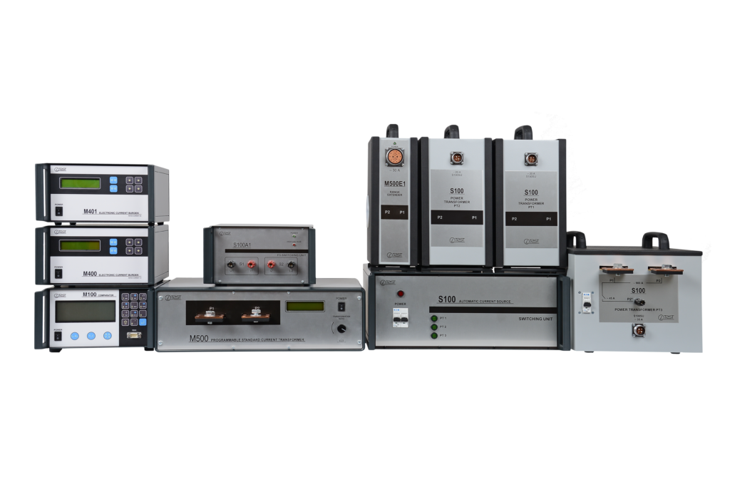
COMPLETE MEASUREMENT SYSTEM
OLTEST LLC also supplies PC-controlled CT and VT calibration facilities for specific customer requirements, including:
- М100 Comparator
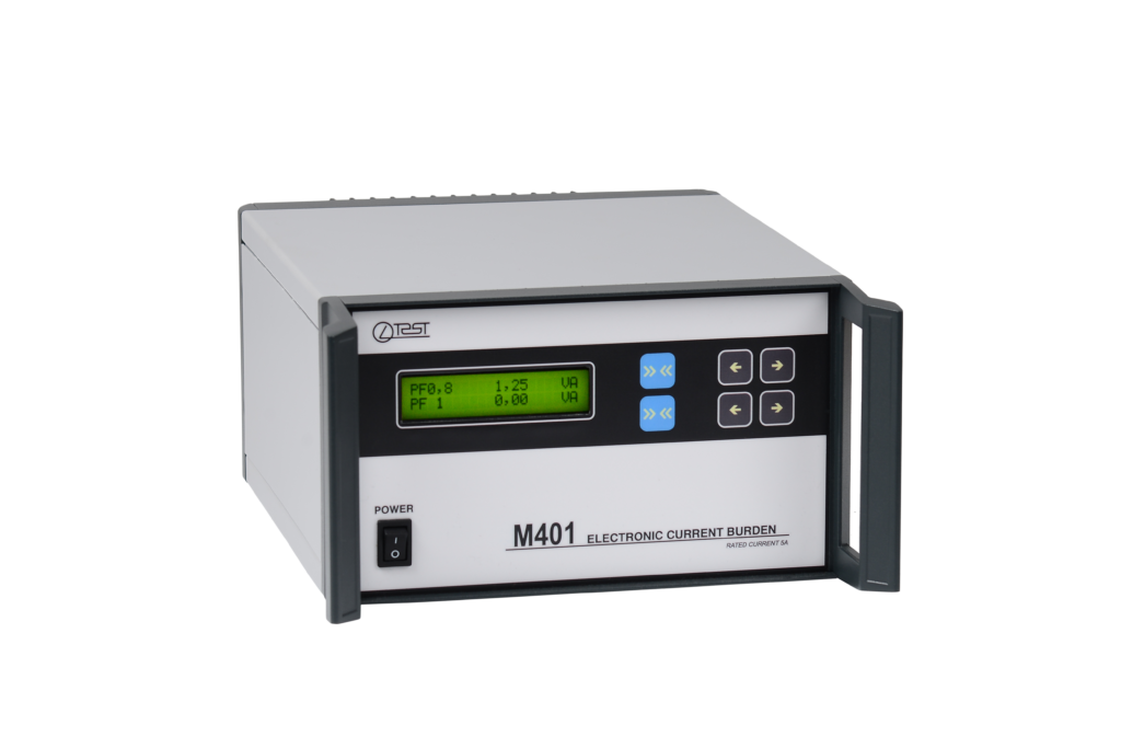
- M402 Electronic Current Burden
- M410 Electronic Voltage Burden
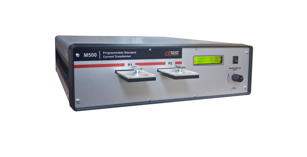
- M500 Programmable Standard Current Transformer
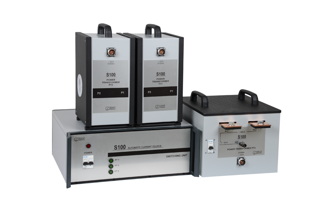
- S100 Automatic Current Source
APPLICATIONS
Comparator M100 is used by:
- Current and Voltage Transformers manufacturers
- On-site testing Current and Voltage Transformers
- Calibration laboratories
- Metrology institutes
|
Value |
Range | Accuracy |
Condition |
|
| Voltage error, εU |
-15…15 % |
± (0,005·|εU|+1·10-4+10-4·|∆φU|) % | 20 V ≤ US ≤ 240 V | |
| ± (0,005·|εU|+1·10-3+10-4·|φU|) % |
6 V ≤ US < 20 V |
|||
| Phase displacement, ∆φU |
-300…300 min |
± (0,005·|∆φU|+0,05+5·10-2·|εU|) min | 20 V ≤ US ≤ 240 V | |
| ± (0,005·|∆φU|+0,1+5·10-2·|εU|) min |
6 V ≤ US < 20 V |
|||
| Current error, εI |
-15…15 % |
± (0,005·|εI|+2·10-4+10-4·|∆φI|) % | 1 А ≤ IS ≤ 7,5 А | |
|
± (0,005·|εI|+3·10-3+10-4·|∆φI|) % |
0,05 А ≤ IS < 1 А |
|||
| ± (0,005·|εI|+1,5·10-2+10-4·|∆φI|) % |
0,01 А ≤ IS < 0,05 А |
|||
| Phase displacement, ΔφI |
-300…300 min |
± (0,005·|∆φI|+0,03+5·10-2·|εI|) min | 0,25 А ≤ IS ≤ 7,5 А | |
| ± (0,005·|∆φI|+0,5+5·10-2·|εI|) min |
0,01 А ≤ IS < 0,25 А |
|||
| Active (reactive) VT burden power, P (Q) |
0…500 W (VA) |
± [0,005· √(P2+Q2)+USr2·10-7] W (VA) | 50 V ≤ US ≤ 240 V | |
|
± [0,005· √(P2+Q2)+USr2·2·10-7] W (VA) |
30 V≤ US < 50 V |
|||
| ± [0,005· √(P2+Q2)+USr2·10-6] W (VA) |
6 V ≤ US < 30 V |
|||
| Active (reactive) CT burden power, P (Q) |
0…500 W (VA) |
± [0,005· √(P2+Q2)+ISr2·3·10-4] W (VA) |
0,01 А ≤ IS ≤ 7,5 А |
|
| Active (reactive) VT burden conductivity G (B) |
0…0,05 S |
± [0,005· √(G2+B2)+1·10-7] S | 50 V ≤ US ≤ 240 V | |
|
± [0,005· √(G2+B2)+2·10-7] S |
30 V ≤ US < 50 V |
|||
| ± [0,005· √(G2+B2)+1·10-6] S |
6 V ≤ US < 30 V |
|||
| Active (reactive) CT burden resistance R (X) |
0…200 Ω |
± [0,005· √(R2+X2)+3·10-4] Ω |
0,01 А ≤ IS ≤ 7,5 А |
|
| Rated secondary current |
1…5 A |
– |
– |
|
| Current range | М100.1 |
1…120 % |
± 0,5 % |
– |
| М100.2 |
1…200 % |
|||
| Rated secondary voltage |
100/3…110 V |
– |
– |
|
| Voltage range |
20…120 % |
± 0,5 % |
– |
|
|
ɛU – VT voltage error, %, ΔφU – VT phase displacement, min ɛ I – CT current error, % Δφ I – CT phase displacement, min USr – rated value of the secondary voltage of tested VT, V P – value of active power measurement result, W Q – value of reactive power measurement result, VA |
ISr – rated value of the secondary current of tested CT, A IS – secondary current US – secondary voltage G – value of conductance measurement result, S B – value of susceptance measurement result, S R – value of burden resistance measurement result, Ω X – value of burden reactance measurement result, Ω |
|
Power mains Rated voltage Frequency |
220/230 V 50/60 Hz |
|
Operating temperature Relative humidity Size (W×H×D) Weight (Main unit) |
0…40 °C up to 80 % non-condensing 250 × 150 × 350 mm 5 kg |
|
Standards Safety EMC |
EN 61010-1:2010 EN 61326-1:2013 |
* The manufacturer reserves the right to change the characteristics of the device.